Multi-split Systems and Variable Refrigerant Volume (VRV) Systems |
Home |
There are many manufacturers of multi-split systems and variable refrigerant volume (VRV) systems throughout the world and it is important that the designer / specifier / building owner has some practical understanding of their uses and limitations. These systems vary considerably from manufacturer to manufacturer particularly with reference to their operating principles, noise levels and the type of indoor units used.
These systems have come of age in the last 5-10 years and are particularly popular because they require less outdoor plant space than conventional systems, require smaller service ducts and ceiling voids than ducted systems, are less disruptive to fit in existing buildings (particularly when occupied), are able to cool and heat through common pipework and most of the systems capable of providing heating and cooling simultaneously, heat recovery is inherent.
The systems referred to here all use refrigerant as the cooling / heating medium rather than chilled water / hot water as is used in conventional hydraulic systems circulated by pumps.
Condensing units are used externally when cooling only is required and heat pumps are used externally when both cooling and heating are required.
Multi-split Systems |
The traditional 'split system' is also known colloquially and more descriptively as a 'one to one split system', meaning one external condensing unit / heat pump is connected by refrigerant pipework to one indoor cooling / cooling and heating unit.
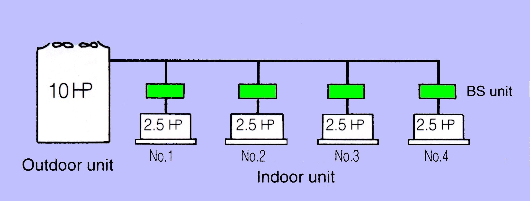
The multi-split system uses one external unit which is connected to several indoor units. The multi-split system takes a number of different forms and it is essential the designer / specifier understands the limitations of each type of system when considering an application.
Master and slave system (fixed capacity cooling only or heat pump)
One off external condensing unit / heat pump unit is connected to several indoor units as is typical for a multi-split system. One of the indoor units is provided with temperature controller / sensor and acts as master and the other unit(s) acts as slaves. All indoor units will therefore function as the master setting. Master and slave units are suitable for single areas, single rooms or even multiple rooms with very similar heat gains / losses. They are not suitable for individual areas / rooms which have different heat gain / loss characteristics because the master control will sense air temperature for one area / room only and the areas / rooms will overcool or overheat.
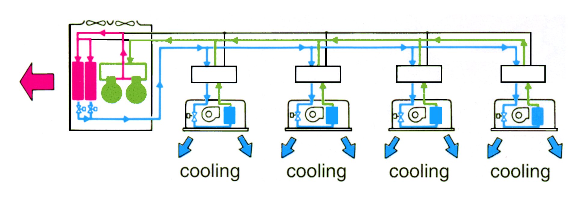
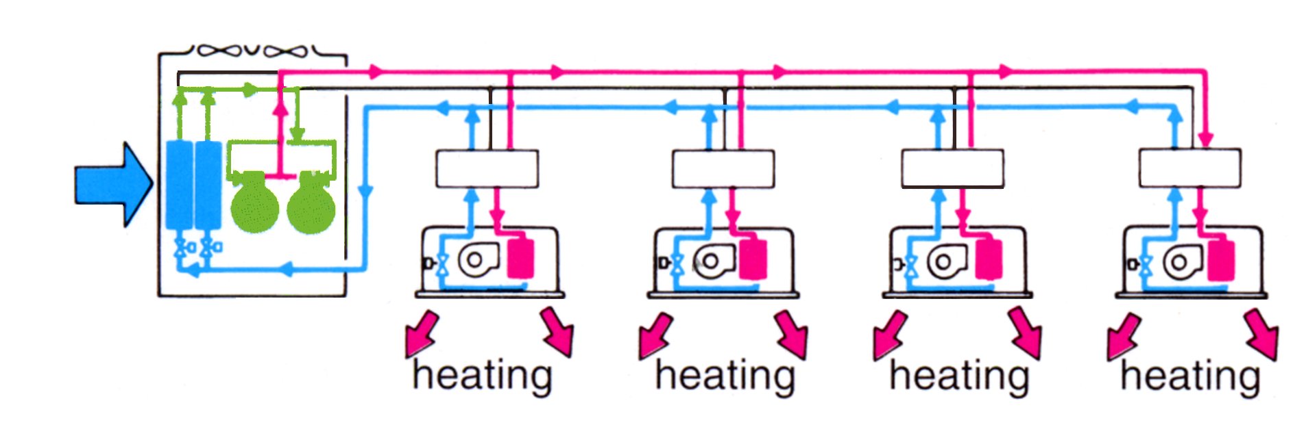
Zoned control units (variable capacity all cooling or all heating - 2 pipe system)
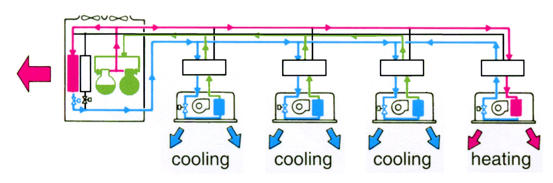
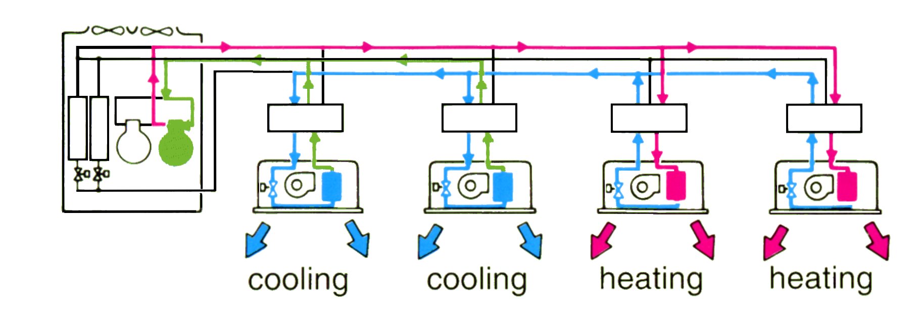
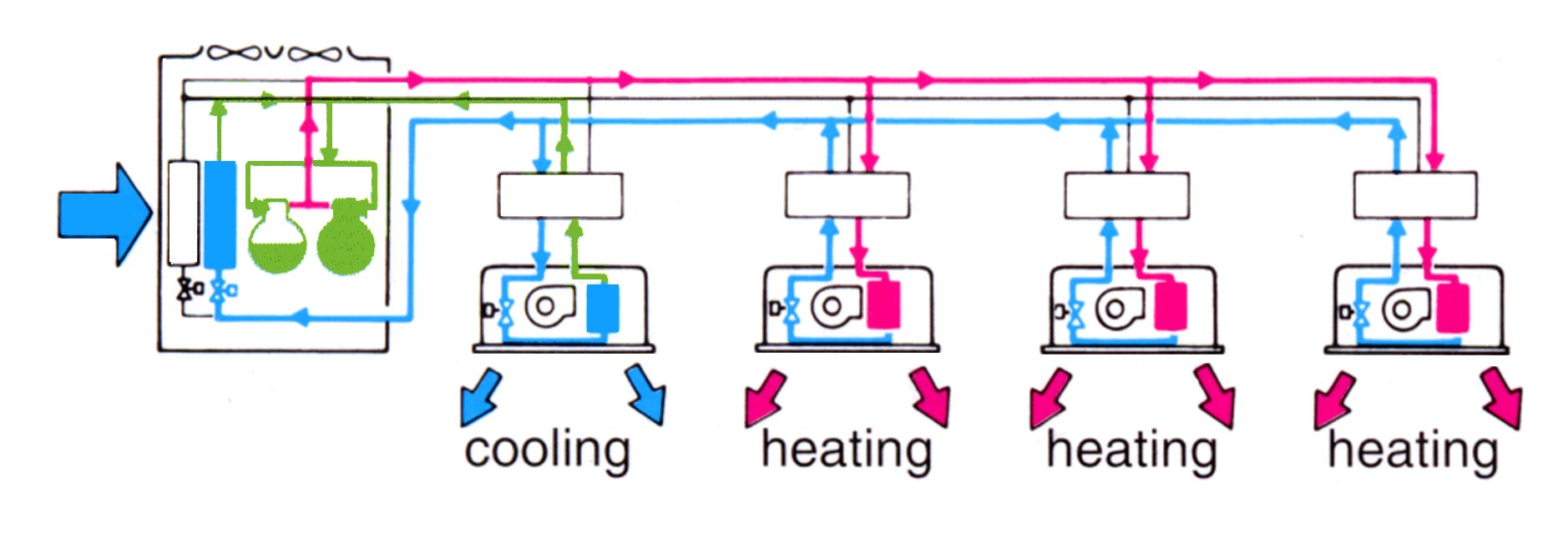
Zoned control units with simultaneous heating and cooling (variable capacity 3 pipe systems)
Refrigerant Pipework Limitations |
The maximum lengths of pipework for all mass produced packaged air conditioning systems is determined by the the compressors ability to overcome the pressure drop and for the system to maintain proper oil return. All 'split' systems therefore have a maximum vertical and total refrigeration pipework length allowable. This is a considerable disadvantage compared with hydraulic systems which are pumped and as the pump may be sized to suit the system, then theoretically, the hydraulic pipework may be run almost infinite distances. It is important the designer / building owner is aware of these limitations. Each manufacturer specifies both the size of the pipework required for their system and the maximum permissible vertical and total refrigerant pipework runs.
Moreover it may not be assumed that these distances will be similar between manufacturers for similar capacity equipment this is often not the case. However a nominal guideline is as follows:
VRV systems and zoned systems generally up to 50 metres vertically and 100mm overall. Typically one outdoor unit may be connected up to a maximum of 16 indoor units.
Indoor Units |
All indoor units used with multi-split systems provide air distribution by mixed flow or tangential fans and come in various forms:
With reference to (e), the size and type of the fan motors in these units vary considerably from manufacturer to manufacturer and this determines the extent of the ductwork allowable which is a function of the static pressure of the fan. Silencers may also be provided within the ductwork for very low noise levels required in such spaces as recording studios, but again the fan static pressure available has to be checked carefully so the pressure drop through the silencers may be overcome by the fan.
Outside Air |
The introduction of outside air to all 'split' systems is often a problem (typically 8 l/s per person is required, recommended by CIBS). To overcome this problem some manufacturers offer a heat recovery unit which provides heat exchange between incoming outside air and the exhaust air from the air conditioned space, independently of the indoor units. With these systems an equal quantity of outside air and exhaust air is supplied and then exhausted from the air conditioned space. The supply and exhaust air passes over a heat exchanger so heat is recovered from the exhaust air and used to heat or cool the outside air. This solution has the limitation that air is introduced to the space at two different temperatures, i.e. that of the indoor unit and that of the heat recovery unit. If possible it is always ideal to introduce outside air to the indoor unit.
Applications |
The systems are therefore suitable when there is a clearly defined heating and cooling season i.e. cooling only required throughout the building or heating only required throughout the building. With the increased prevalence of heat producing I.T. equipment within buildings this needs some consideration because if one particular part of a building requires cooling 12 months of the year this system would not be appropriate. The solution in this case would be either to use a V.R.V heat recovery system or have an independent system dedicated to that part of the building.
With the larger zoned systems typically it would be possible to connect up to 16 indoor units to one external unit. With most manufacturers the units may be mixed i.e. an assortment of ducted, cassette, wall, floor, and ceiling units connected to the one outdoor unit.
Acknowledgements |