Regulating the Condensing Pressure |
The air-cooled condenser | How to regulate the condensing pressure | Cut-in and out of one or several fans | Cycling of the fans by Pressure or thermostat control | Condenser Fan speed control | Modulating Damper In The Air-Stream | Adapting the effective inner condenser surface | Automatic water regulating valve | Acknowledgements
Air-cooled condensers have been accepted and in general use in small refrigeration systems for many years. In large refrigeration systems it has, however, been normal to use water-cooled condensers of different designs.
Of course, water-cooled condensers are still used in many refrigeration systems, but in recent years there has been a clear trend towards air-cooled condensers in both small and large refrigeration systems. This is due to several factors, of which can be mentioned, for example, increasing prices of mains water, increased difficulties in obtaining sufficient water supplies, increased wages for maintenance work.
The air-cooled condenser |
The air-cooled condenser is a heat exchanger where the heat is removed from the compressed gas from the compressor and is absorbed by the quantity of air which is passed over the heat transmission surface by a fan. The heat exchange between the hot pressure gas and the air results in a temperature fall and hence condensation of the gas in the condenser.
Sizing condensers for both refrigeration and air-conditioning systems offer some problems which must be solved for the refrigeration systems to give both technically and economically satisfactory operation. The problems are caused by the varying temperatures of the air or water used for cooling the condenser and the varying load on the refrigeration plant. If the refrigeration system has been correctly sized, it will give satisfactory operation even at extremely high ambient temperatures. Most systems will, normally, operate at an ambient temperature which is lower - in the case of some systems even considerably lower - than the temperature for which the systems have been sized. The problems thus caused are, therefore, often very complex to solve. The problem is that the condenser must be sized for satisfactory operation at maximum ambient temperatures, and at the same time it must be of such dimensions as to give satisfactory operation of the system also at minimum ambient temperatures.
The reduction of the condensing pressure has a lower limit if it is desired to achieve satisfactory operation of the refrigeration system. The condensing pressure must be of such an order that: -
Under normal conditions a sufficiently high condensing pressure will be considerably lower than the maximum condensing pressure at the maximum ambient temperature.
How to regulate the condensing pressure |
The maintenance of a sufficiently high condensing pressure can be ensured in several ways. These ways can, fundamentally, be divided into two main groups.
Group 1
Regulation of the quantity of cooling media through the condenser.
Among the forms of regulation in this group can be mentioned e.g.:
- Cut-in and out of one or several fans by one or more pressure controllers connected to the high-pressure side of the system (see Fig. 1).
- The use of a speed regulator in connection with the fan motor so that a variable speed is obtained, depending on the condensing temperature (see Fig. 2).
- A modulating damper in the air-stream to reduce the airflow (centrifugal fan models only),
- Automatic water control valve.
Group 2
Regulation of the condensing pressure by adapting the effective inner condenser surface F and bypass of hot gas to the receiver (see Fig. 3).
Cut-in and out of one or several fans |
Cycling of the fans by Pressure or thermostat control |
On direct-drive condensers with more than one fan, head pressure control may be achieved by stopping and starting the fans on demand by a pressure sensor or temperature sensor connected to the condenser coil block.
As the condensing pressure or temperature fall is, due to a low ambient, then the sensing dictates to a step controller that one fan be stopped. This reduction in air volume reduces the condenser performance and tends to raise the condenser pressure. If the ambient continues to fall then subsequent reductions in condensing pressure or temperature will dictate that further fans be stopped in order to maintain a sufficiently high condensing pressure.
Selection of suitable differentials on the controls must be made to ensure that unnecessary cycling of the fans does not occur and the expected range of operation is covered.
Condenser Fan speed control |
Fan speed control using variable-speed motors and/or drives, two-speed motors, or additional lower power pony motors (small modular motors on the same shaft). Two-speed fan motors usually operate at 100 and 50% fan speed, which provides 100% and approximately 60% condenser capacity, respectively. With the fans off and the water pump operating, condenser capacity is approximately 10%.
Special capacitor start, capacitor run motors can be fitted to direct-drive condensers facilitating use from 100 per cent down to approximately 20 per cent of full speed. A thermistor senses the condensing temperature on the coil block and transmits this to the controller which trims the output voltage to the fan motors so that an appropriate fan speed adjustment is made.
This form of control can be applied to one or more fan motors to give smooth reduction of performance down to approximately 25 per cent of condenser design rating.
Often, two-speed fan motors or pony motors provide sufficient capacity control, because it is seldom necessary to hold condensing pressure to a very tight tolerance other than to maintain a certain minimum condensing pressure to ensure refrigerant liquid feed pressure for the low-pressure side and/or sufficient pressure for hot gas defrost requirements. Variable-speed motors including necessary drives are more expensive but offer a full range of speed control for those applications requiring close control on condensing pressure. Also, they are often justified economically from energy savings.
Careful evaluation of possible critical speed problems should be reviewed with the manufacturer on all variable-speed motor applications.
Modulating Damper In The Air-Stream |
Modulating air dampers also offer closer control on condensing pressure, but they do not offer as much fan power reduction at part load as fan speed control. However they are able to prevent airflow across the condenser by natural convection, which in some instances this alone can result unacceptably low head pressure in very low ambients.
The full modulating Pressure Operator is a bellows motor designed to provide uniform response to pressure changes. These pressure changes are converted into shaft movements.
The Pressure Operator (connected directly to the high-pressure side of the compressor) monitors the compressor pressure. If the head pressure drops, putting stable operation at risk, the operator modulates the damper closed. Restricting the airflow through the condenser coil - producing less cooling of the condenser and thereby providing proper head pressure as the ambient temperature declines.
| Economical | Completely eliminates electric actuators, pressure switches and wiring. |
| Fully modulating | the Pressure Operator monitors compressor pressures to modulate damper louvers. There is no "step action" as in other devices. |
| Simplicity of design | the heat treated beryllium copper bellows motor is contained in a hermetically sealed case. No seals or gaskets to leak. |
| Maintenance-free | the Pressure Operator is factory lubricated. Additional lubrication, or other servicing, is not required under normal conditions. |
| Ease of application | installation is fast and easy. The Pressure Operator is connected to a point on the high pressure side of the unit (between the condenser and receiver) by 1/4" O.D. tubing, |
Dampers should be as nearly friction-free as possible and normally as balanced as possible when subjected to the fan loading. Small amounts of friction drag, such as produced by loose fitting nylon or 'oilite' bearings and normal linkage that does not bind, is not acceptable. Generally, there is sufficient vibration caused by the running fan to eliminate the frictional effect and cause it instead to act as a snubber to prevent hunting. A good installation in operation might require up to 5 seconds returning to any normal position after being forced out of that position manually.
Successful applications have been made to dampers that are unbalanced either by their own centre of gravity or by the fan loading on the blades. It is suggested that the field application engineer does not attempt such on application unless he is fully familiar with mathematics of the entire operator - damper system. It is much easier to obtain fully balanced dampers in the beginning.
Air flow control.
It should be remembered that air restriction through dampers is not linear with blade rotation.
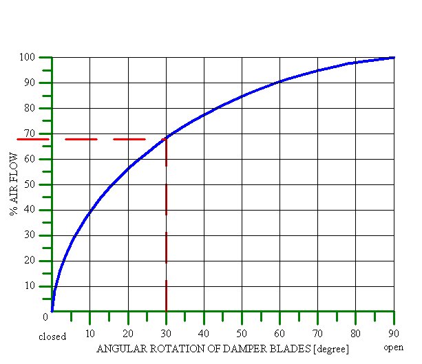
It can be seen from the above that nearly 70% of the control of flow occurs during the first 30º of damper opening. Dampers are rarely called upon to operate in a fully closed position except under low ambient start up conditions.
Their closed position at this time aids in a much quicker build up of head pressure. In this connection, it has been found by one manufacturer, who has several thousand of these units in the field for several years, that ice and snow have little effect on the operation of the unit. The subject units have pull through horizontal fans with horizontally mounted dampers directly exposed to snow fall. It has been observed that condenser heat driven against the damper any snow or ice quickly melts the obstruction and allows normal operation of the pressure operator.
Fan operation.
Many propeller type fan blades have operational characteristics that tend to load the fan motor beyond its rated capacity when airflow is completely blocked. Field, applications should be checked for this condition. An amperage measurement should be taken with the damper blocked shut to be sure the maximum rated fan current is not exceeded. Should this condition exist there are several means of alleviating the problem. First, the may be blocked or stopped at the minimum flow condition which does not overload the fan. This will generally allow desirable head pressure control except in the most severe low ambient conditions. Another solution is to control fan operation through a pressure control which will open the, fan circuit when liquid line pressure decreased to a value slightly above that where the fan motor will become overloaded. The control cut-in value should ordinarily correspond to a pressure slightly above the full open position of the damper. The best solution and the one used by most original equipment manufacturers, is to provide the condensing unit with a fan which has non-loading characteristics and therefore creates no problem. Centrifugal blowers are not subject to this problem.
Installation.
Pressure connection to a condensing unit should be made, in the 1iquid line or receiver to prevent damage to the bellows from compressor pulsations. Protection from the weather should be used to prevent water from entering the control at the shaft end, mount control with shaft in downward position. Damage to the bellows could result from water freezing inside the control. Natura1ly torches should not be applied to the body of the control.
Adapting the effective inner condenser surface |
Fig. 3. Condensing pressure regulation by backing up the refrigerant liquid in the condenser.
Operating principle of the system
This form of regulation can be effected in many different ways which are all basically identical, however. It is based on the fact that charging the condenser with refrigerant liquid results in a reduction of the effective condenser area F, making it possible to maintain the condensing pressure.
The liquid back up regulator is fitted in the condensate line between the condenser and the receiver. It only regulates the flow depending on the inlet pressure.
If the condensing pressure falls below the setting of the liquid back up regulator, its degree of opening is reduced correspondingly. Hence the condenser is filled partially with liquid, and the required condensing pressure is maintained.
Because of the heavily subcooled refrigerant liquid, the receiver pressure has to be maintained by a supply of hot gas. The hot gas is supplied to the receiver by a line bypassing the condenser.
Fixed pressure differential regulator -The degree of opening of hot gas bypass regulator is determined exclusively by the differential pressure across the valve. Hot gas bypasses the condenser whenever the receiver pressure is the predetermined pressure below the condensing pressure. (The receiver pressure floats up and down as the discharge pressure floats up and down.
Adjustable outlet pressure regulator, The degree of opening of hot gas bypass regulator is determined exclusively by its outlet pressure i.e. the receiver pressure. Due to the fact that the hot gas bypass regulator can be adjusted, directly adjustable control of the receiver pressure is possible.
Summer operation at high air temperatures, normally, has the effect of the condensing pressure exceeding the setting of the liquid back up regulator, therefore, it would completely open, and so there is no liquid backup in the condenser, it is free to drain into the condenser. Hence the receiver pressure would be close to that of the discharge pressure. In the case of the pressure differential regulator, the difference in pressure would be inadequate to open the valve, therefore no hot gas would bypass the condenser. In the case of outlet pressure regulator, the receiver pressure would exceed the setting of the regulator, therefore the outlet pressure regulator would remain closed and no hot gas would bypass the condenser.
To determine the liquid charge of the system, it is necessary to pay attention to the partial charge in the condenser during winter operation. Determining the additional refrigerant charge is done by multiplying the total length of the condenser pipes, including the length of the condensate line to the hot gas bypass regulator, by the quantity of refrigerant in kg. per metre of pipe for the pipe size in question (see table 1).
Table 1. Quantity of refrigerant in kg/m pipe
|
|
|
|||
|
|
|
|
||
|
|
|
|
|
|
|
|
|
|
|
|
|
|
|
|
|
|
When sizing the receiver, attention should be paid to the fact that this additional charge must be contained in the receiver during summer operation.
As a result of the temperature conditions in the system - especially during the standstill periods of winter operation -undesirable liquid migration may occur. This state can be remedied by means of check valves. In particular, precautions should, of course, be taken against undesirable liquid migration to the compressor.
Automatic water regulating valve |
Acknowledgements. |
Danfoss.
RobertShaw.
Searle.
Parker.